WFilter Deployment Guide
3.1
- Author:
- IMFirewall Inc.
- HomePage:
- http://www.imfirewall.com/en
Contents
1) Minimum Requirements
- CPU: 1.0GHz Intel Celeron or equivalent
- RAM: 256M
- OS: Windows2000/XP/2003
- Microsoft IE6.0 or later
2) Recommended Requirements
- CPU: 1.8GHz Intel Pentium4
- RAM: 512M
- OS: Windows2000/XP/2003
- Microsoft IE6.0 or later
3) How to calculate the hard disk and memory space WFilter needed?
The memory cost is related to the computer number you are monitoring.Each computer
costs about 1M RAM.
- RAM needed = computer number(N) * 1M
Each monitored computer costs about 2M hard disk space one day if you turn record level on.
- Hard disk space needed = computer number(N) * 2M * days
| Componment Name |
Describe |
Default Install Directory |
| WFilter_trial.exe |
Main installation package. Installed list:
1. Service: WFilterd.
2. Process: startsys.exe,webservd.exe. |
C:\Program Files\IMFirewall\WFilter |
- 1.Before you install WFilter software, please make sure you remove all other network sniffing programs or earlier version of WFilter from your computer.
- 2.WFilter software requires the running computer to open TCP port 9090 and 9091. Many firewall program prevents unauthorized program from opening a local port. Therefore it is recommended you shall adjust your firewall settings before installing WFilter.
- 3.WFilter requires a web browser to use its web interface. A browser version like IE 5.5 or higher is recommended. Using older browser may cause WFilter's web interface display incorrectly.
1) Introduction
WFilter can be installed on a single Windows machine for a small network.
WFilter supports TCP/IP-based networks only. If your network uses both TCP/IP and
non-TCP protocols, only those users on the TCP/IP portion of your network will be filtered.
Network Considerations
- 1.WFilter must be deployed in the network at a single location where it can monitor all
Internet traffic on the internal network.How to monitor all Internet traffic?
- 2.The machine with WFilter installed shall be able to communicate with other computers.
2) Deployment Recommendations
Figure 4.1 provides a synopsis of small network deployment. You only need to install WFilter at a single location
where it can monitor all Internet traffic of the internal network.

Figure 4.1
1) Introduction
In a medium network(500-2500 users), WFilter should be distributed on two or more dedicated machines, depending on
your operating environment. These dedicated machines can use a central database for data storage.
We recommend one dedicated machine monitor no more than 500 computers.
Network Considerations
- 1.WFilter must be deployed in the network at a single location where it can monitor all
Internet traffic on the internal network.How to monitor all Internet traffic?
- 2.The machine with WFilter installed shall be able to communicate with other computers.
- 3.The machine with WFilter installed shall be able to communicate with the database server.
2) Deployment Recommendations
Figure 4.2 provides a synopsis of medium network deployment. All dedicataed machines of WFilter use a same
network database.
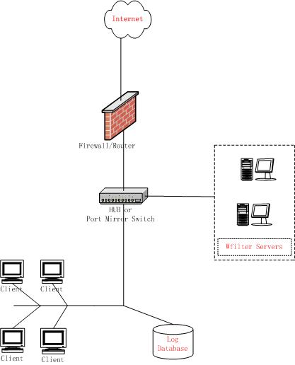
Figure 4.2
1) Introduction
In a large network(2500+ Users), WFilter should be distributed on two or more dedicated machines, depending
on your operating environment. The deployment on dedicated machines is the same as a medium network deployment.
Distributed enterprises are corporations with large numbers of remote locations, ranging from dozens to thousands
of small offices. Some of these organizations use a decentralized network topology that provides each remote office
with its own Internet connection.WFilter Enterprise can be deployed regionally and communicating over the Internet.
Or you can install WFilter in each office separately. You also can apply uniform filtering
policies to hundreds of remote offices from a central location.
Network Considerations
- 1.WFilter must be deployed in the network at a single location where it can monitor all
Internet traffic on the internal network.How to monitor all Internet traffic?
- 2.The machine with WFilter installed shall be able to communicate with other computers.
- 3.The machine with WFilter installed shall be able to communicate with the database server.
2) Deployment Recommendations
Figure 4.3 provides a synopsis of large network deployment. Several dedicataed machines of WFilter use a same
network database.
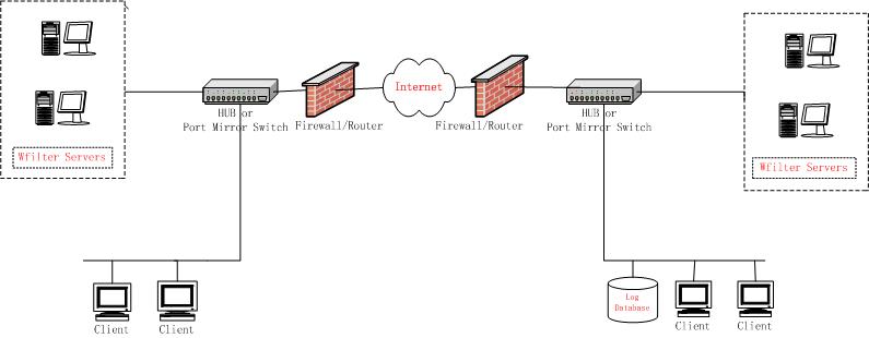
Figure 4.3
A single segment network is a logically connected nodes operating in the same portion of the network. These nodes
can be PCs, printers, other networked devices. In a such a network, WFilters must be installed where they can monitor
Internet traffic across the entire network. You shall set the monitor mode to "by MAC address" in "Monitoring Settings".
Below are some typical network environments:
As in Figure5.1.1,local computers use a wireness router to connect to the Internet.Under this type network, it requires
a broadcasted hub or a port mirroring switch between gateway and switch.And the machine with WFilter installed shall connect
to the hub or the monitor port of the port mirroring switch.
As most broadcasted hub only works in 10Mb speed,we recommend you use a port mirroring switch if your internet bandwidth
larger than 4Mb.
Recommended hub: TPLINK's TL-HP5MU, recommended port mirroring switch: TPLINK's TL-SF2005.
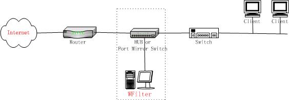
Figure 5.1.1
You may monitor your wireless lan by sniffing on your wireless card directly. If your network use both wireless network
and wireness network.You need to add a wireness router and a broadcasted hub(or port mirroring switch).
Network Topology:
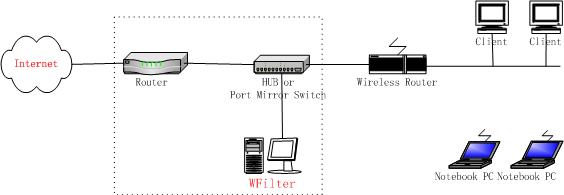
Figure 5.1.2
If your gateway runs a windows system(Windows2000,Windows XP,Windows2003 Server),you may install WFilter on this computer
to monitor the whole network.
If you prefer not to install the software on gateway or your gateway is running Linux. You can insert a broadcasted hub
between the switch and gateway, or create a port mirror on the switch.
Network Topology:
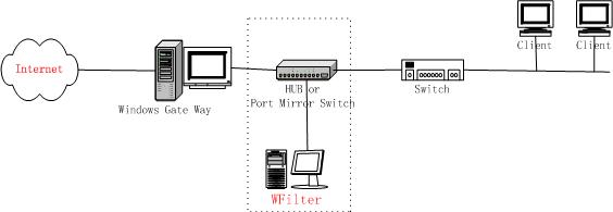
Figure 5.1.3
Depending on the device connecting multiple network segments, some traffic may not be sent to all segments. A router,
bridge or smart hub may serve as traffic control, preventing unneeded traffic from being sent to a segment. In such a
situation,we can not use "by MAC address" mode because a MAC address will related to more than one computer.
We have two solutions for you:
You can put WFilter at a single location and use "by IP address" mode.But this will cause some trouble if your users
change their IP address rapidly.We suggest you use "IP-MAC binding" to avoid unauthorized change of IP address.
As in Figure 5.2.1, it requires a broadcasted hub or a port mirroring switch between gateway and switch.And the machine
with WFilter installed shall connect to the hub or the monitor port of the port mirroring switch.You also need to set monitor
mode to "by IP address".
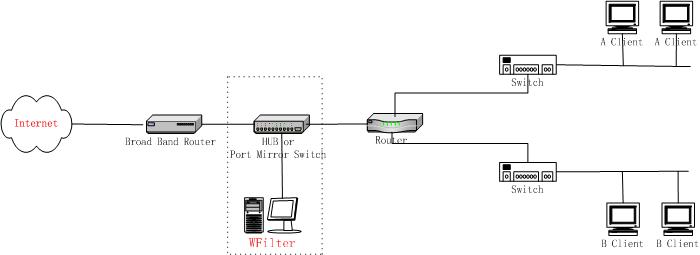
Figure 5.2.1
The second solution is deploying WFilter in each network segment.And all the dedicataed machines of WFilter use a same
network database.
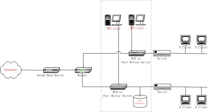
Figure 5.2.2
Basically,a computer connected to a switch or a route can only receive its own traffic.To monitor other computers,your
machine shall be able to monitor other computer's Internet traffic.
A broadcasted hub is a data packet repeater commonly used in broadcast networks. In a broadcast network, a node will send a packet
that traverses through every other node until the recipient accepts the packet. Every node in the network will conceivably
receive this packet of data until the recipient processes the packet. In a broadcast network, all packets are sent in this
manner.So each computer connected to a broadcasted hub can monitor other computers.(Recommended Hub: tplink's TL-HP5MU)
In a switched network, packets are not broadcasted, but are processed in the switched hub which, in turn, will create
a direct connection between the sending and recipient nodes using the unicast transmission principles. This eliminates
the need to broadcast packets to each node, thus lowering traffic overhead.
The advent of switched networks resulted in Network IDS having great difficulty in promiscuously monitoring their networks.
This was overcome by configuring a switch to replicate the data from all ports or VLAN's onto a single port. This function
has a multitude of names including: Port Mirroring, Monitoring Port, Spanning Port, SPAN port and Link Mode port.
Generally Port Mirroring usually indicates the ability to copy the traffic from a single port to a mirror port but disallows
any type of bidirectional traffic on the port.
Spanning Port usually indicates the ability to copy traffic from all the ports to a single port but also typically disallows
bidirectional traffic on the port. In the case of Cisco, SPAN stands for Switch Port ANalyzer.
Some switches do not allow SPAN ports to transmit packets, this is an issue if you wish to use WFilter block features.
As described above,to monitor all Internet traffic,should consider two conditions:
- The machine with WFilter installed shall be connected to a broadcasted hub or the mirror port of a switch.
- All Internet traffic passes through this broadcasted hub or switch.
Usage
A broadcasted hub is a data packet repeater commonly used in broadcast networks.
Most broadcasted hubs provide a uplink port to connect with a up layer device.You shall connect the up layer device to
the uplink port of the hub(Note: Do not use the nearby port with the uplink).
As in Figure6.2:
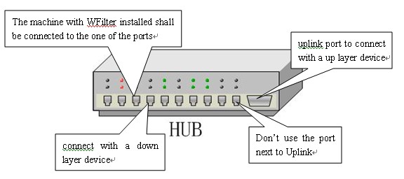
Figure 6.2
HUB's Speed Analysis
Most broadcasted hubs only work in 10Mb speed,and all the computers connected to the hub will share the bandwidth.
For example, if two computer connected, each will have 5Mb bandwidth.So we recommend you use a port mirroring switch
if your internet bandwidth larger than 4Mb.
The machine with WFilter installed shall be connected to the mirror port of a switch.As in Figure6.3.
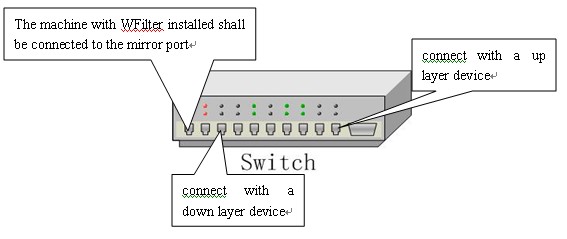
Figure6.3
Introduction
Different switch provide different configuration.Below we provide some common switchs' port mirroring configuration.
1. Huawei Switch
How to use "Huawei Lanswitch View" management system to add a mirror port:
Click "Device Setup" or "Stack Setup".
Click "Port Mirroring".
Click "Add" button, for stack , click "switch" and choose a switch from the list.
Click "Reflect from" and choose the ports been mirrored.
Click "Reflect to" and choose the mirror port.
2. 3COM Switch
In 3COM switch,port mirroring is named as "Roving Analysis".The port been mirrored is called as "Monitor Port", The mirror port is
called as "Analyzer Port".Configuration commands:
Define an analyzer port
"feature rovingAnalysis add", or "f r a"
For example:
Select menu option: feature rovingAn alysis add
Select analysis slot: 1
Select analysis port: 2
Define monitor ports
"feature rovingAnalysis start" or "f r sta"
For example:
Select menu option: feature rovingAn alysis start
Select slot to monitor (1-12): 1
Select port to monitor&nb sp; (1-8): 3
Stop port mirroring
"feature rovingAnalysis stop" or "f r sto"
3. Cisco CATALYST Switch
CISCO CATALYST has two series. The mirror port is named as "analysis port".
1. Catalyst 2900XL/3500XL/2950(CLI based)
port monitor
For example:F0/1,F0/2,F0/5 belong to VLAN1
interface FastEthernet0/1
port monitor FastEthernet0/2
port monitor FastEthernet0/5
port monitor VLAN1
2. Catalyst 4000/5000/6000(IOS based)
set span
For example:6/1,6/2 belong to VLAN1.6/3,6/4,6/5 belong to VLAN2.
set span 6/1,6/3-5 6/2
4.DELL Switch
- Use the user interface and modify these parameters :
- Destination Port: mirror port
- Source Port: ports being mirrored.
- Add: Add port mirroring.
- Type:Port mirroring type, Possibly choices:
- "RX"-Only monitor incoming traffic.
- "TX"-Only monitor outgoing traffic.
- "Both"-Monitor all traffic.
Steps:
1. Choose the "Destination Port" in the "Port Mirroring" dialog and click "Add".
2. Define the "Source Port" and "Type".Then click "Apply Changes".
3. Define the morror port.
CLI command example:
Console(config)# interface ethernet 1/e1
Console(config-if)# port monitor 1/e8
Console# show ports monitor
Source port Destination Port Type Status
----------- ---------------- ----- -------
1/e1 1/e8 RX, TX Active
5.NetCore Switch
The netcore switch provides four monitor state:
Off-Close port mirroring
Rx-Monitor incoming traffic.
Tx-Monitor outgoing traffic.
Both-Monitor all traffic.
Open NetCore's super-terminal,press "5" to enter the port mirror configure dialog, then
press "1" to set the port mirror state.
For example:
1. Set status(1,off, 2.Rx, 3.Tx, 4.Both):4
2. Set mirror port:1
3. Set port being mirrored:8
Press "Esc" to return.
6.Avaya Switch
Commands:
{set|clear } Port Mirror
set port mirror:
set port mirror source-port
mirror-portsampling { always } [ max-packets -sec] [ piggyback-port ]
disable port mirror:
7.Intel Switch
The port being mirrored is called as "Source Port".
The monitor port is called as "Mirror Port".
Steps:
- Click "Mirror Ports" in "navigation" menu.
- Select source port in the "Configure Source" column.
- Set the mirror port.
- Click "Apply" to apply the changes.
Monitor mode:
1. Always: Monitor all traffic.
2. Periodic: Monitor all traffic in defined interval.The interval can be set in "Sampling Interval configuration".
3. Disabled: Close port mirroring.
Please refer to the switch's documents for more information.